In this post I describe a method for testing the network between virtual machines, using python scripts. The rationale is to avoid costly elements such as virtual machines or even containers.
Introduction
As I mentioned in the previous post, I am working on Dragonflow[1] and Openstack. Dragonflow is a distributed SDN controller, implementing Openstack’s Neutron API. Loosely speaking, it configures the virtual networking in Openstack compute nodes. As part of its development, we wanted a simple light-weight method to test the networking.
The most intuitive solution is to have Virtual Machine (VM) connect to the network and verify the packets sent from one virtual host correctly arrive at the other virtual host.
There are a number of issues with this solution:
-
Virtual machines are heavy. Booting them can take tens of seconds, and even minutes.
-
A virtual machine contains its own network stack, which has to be configured correctly, and used via a specified API. There are solutions to write packets directly to the wire, but we felt they are more complex than what we have constructed.
-
A communication channel between a virtual machine is not trivial. This is not to say it is difficult, just not out-of-the-box. The communication channel has to be constructed on both endpoints.
-
The virtual machine may have its own ideas as to which packets we want to see. It is not difficult to override this, but it’s more effort that has to go into that solution.
With all that in mind, we thought it would be easier to have a simple python script to emulate the VM.
-
The loading of a python script takes up to a few milliseconds.
-
We have raw access to the packet data, and there are python packages that can help parse and process raw packets.
-
The communication can be anything we want, including shared memory in threads, IPC solutions such as multiproc queues or an IPC publish-subscribe method, or even communication via files if all else fails.
-
Having direct control on the data-flow, we can make sure that no packets are discarded, for any reason, without our consent.
The code is freely available in the dragonflow code repository. I may write a code-walk post if there is demand, but I want to concentrate on the high-level parts. The interested reader is invited to read the code itself here:
Technical Background
The weight-lifting is done by Openvswitch[2]. Openvswitch (OVS) is multilayer virtual switch. It supports the OpenFlow[3] configuration protocol, which is what Dragonflow uses to configure it.
The openflow switch specification is available here. Searching for ‘Openflow Switch Specification’ will probably return the latest version (Currently 1.5).
In essence, an openflow switch provides a set of tables. Each table has a set of rules, and for each rule a set of actions. Actions may be to send the packet to another table, or out of a port. A port may be either physical (e.g. Ethernet), internal or virtual (e.g. TAP devices, tunnelling interfaces), or to a controller. When a packet arrives, it is sent to a predefined table for processing.
Dragonflow configures the OVS with information on how to route packets within a subnet, and between subnets on the same network. Subnet-internal routing is done by reading the destination MAC address, and pushing the packet out the correct port. Routing between sunets is done using virtual routers and router ports on top of OVS.
One way to allow a VM to connect to OVS is via TAP interfaces. From the OVS’s point of view, a tap device is a standard network interface. Packets can be received and sent on it as if it were a physical network device.
On the VM side, the network card is implemented by the same TAP device. When the VM puts a packet on the wire, the hypervisor redirects the packet data to the TAP device. The packet placed on the TAP device includes the entire frame, including L2 information such as source and destination MAC addresses.
The python code that simulates the VM opens the TAP device for reading and writing. This is done using the python-pytun[9] library. Once done, the TAP device looks like a run-of-the-mill socket, which can be read and written, seamlessly integrated into the application (Well, almost. See previous post).
Once the python script creates the TAP device, and connects it to the OVS bridge, it looks as if the ‘VM’ has connected. It is ready to send and receive packets. Dragonflow installs flows to handle packets generated by the python code, and send packets targeted to it.
When the python code reads data from the TAP device, it reads an entire frame, including all layers. The python script can then parse this information, and process it accordingly. External libraries, e.g. libpcap and pcapy[4,5], scapy[6], or ryu[7] can help in this department.
When the python code writes data to the TAP device, it is expected to write entire frames as well. This means that the python code will have to synthesise network packets. External libraries can help here as well, such as scapy[6], ryu[7], and packet[8].
To be usable in testing, the python code has to be told the scenario, including what packets to expect, what packets to send, and when anything is supposed to happen. It also needs to know what packets can be received, and what packets raise an error when received.
Therefore, we need a policy. The policy structure we have selected tells each port what packets to expect, and in what order. It tells the python code what to do when each packet is received, i.e. what action to take. It also has a default rule on the policy, i.e. unmatched packet on any rule, and a default action for a packet received on a port with no specifically defined policy.
We have implemented several actions, such as ignore, log, reply, raise an error, stop the policy for a specific port, and stop the entire policy. The latter doesn’t cause an error. That can be done with the raise action.
If the simulation hasn’t ended within, say, 30 seconds, we assume that a necessary packet hasn’t arrived, and fail the test. Otherwise, the stop the entire policy action should have been called.
Basic Architecture
Topology
As a first step, we needed to tell Neutron and Dragonflow what’s the network
structure. We have a Topology class which implements the entire topology.
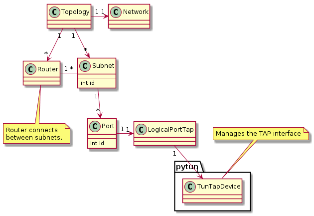
The Topology class contains the complete settings. Since we want to test
network communications, it makes sense to have a single network. The Topology
also includes all the subnets and routers. A Subnet contains all the Ports
on that subnet. A Router is used to communicate between Subnets. A Port
holds the TAP device, so that data can be sent and received.
A Network, Subnet, Port, and Router also contain objects which are used
to communicate with Neutron.
A Subnet and Port have unique IDs, which are deterministic incremental
counters. This way they can be referenced externally, without having to dig
through the topology for the relevant subnet/port.
Policy
This is the policy structure:
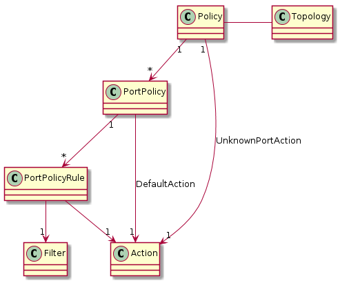
Each Policy contains a PortPolicy per port. Each PortPolicy contains a
list of rules (PortPolicyRule). Each PortPolicyRule contains a Filter and
a list of Actions.
When a packet arrives at a specific port, it is sent to the relevant
PortPolicy, identified by that port’s and its subnet’s IDs. If a PortPolicy
doesn’t exist for that port, the UnknownPortAction is applied.
The packet is then tested against each active PortPolicyRule. If the packet
matches, i.e. the Filter returns true, then the Actions are applied on it.
If the packet hasn’t matched any active rules, the DefaultAction is applied
on it.
When the test is started, the policy calls all its InitialActions, in order.
Specific Tests
ARP Responder
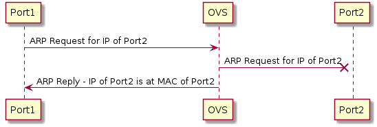
In this test, we want to test Dragonflow’s ARP responder. Dragonflow’s ARP responder captures any ARP requests from any host on the network, and responds if the requested IP exists. The ARP request does not propagate to the other VMs.
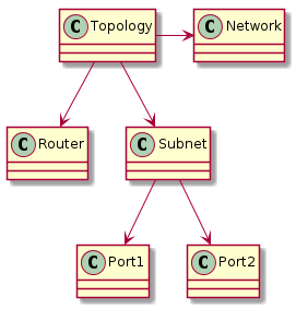
For this test, we need ports with two different IPs. One port sends an ARP request with the other port’s IP. The test will succeed if the first port receives an ARP reply, and the second port will not see the ARP request.
The topology is as follows:
The policy is as follows:
DHCP Client
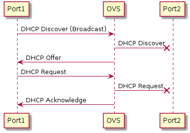
In this test, we want to test Dragonflow’s DHCP responder. Dragonflow’s DHCP responder simulates a DHCP server. The VM sends a DHCP discover message, and the responder is supposed to answer with a DHCP offer. The host then sends a DHCP request, and the responder should reply with a DHCP acknowledge.
Note that this test has not yet been written.
The DHCP packets should not leak to other VMs.
The topology for this test is the same as for the ARP responder test:
The policy is also very similar, but has to be adapted to the two-phase DHCP protocol:
References
[1] https://wiki.openstack.org/wiki/Dragonflow
[2] http://openvswitch.org/
[3] https://www.opennetworking.org/sdn-resources/openflow
[4] http://www.tcpdump.org/
[5] https://pypi.python.org/pypi/pcapy
[6] https://pypi.python.org/pypi/scapy
[7] https://pypi.python.org/pypi/ryu/
[8] https://pypi.python.org/pypi/packet/
[9] https://pypi.python.org/pypi/python-pytun